Date: Fri, 14 Aug 2015 14:11:25 +0200
Thanks a lot for your help !
So you advice me to continue the simulation.
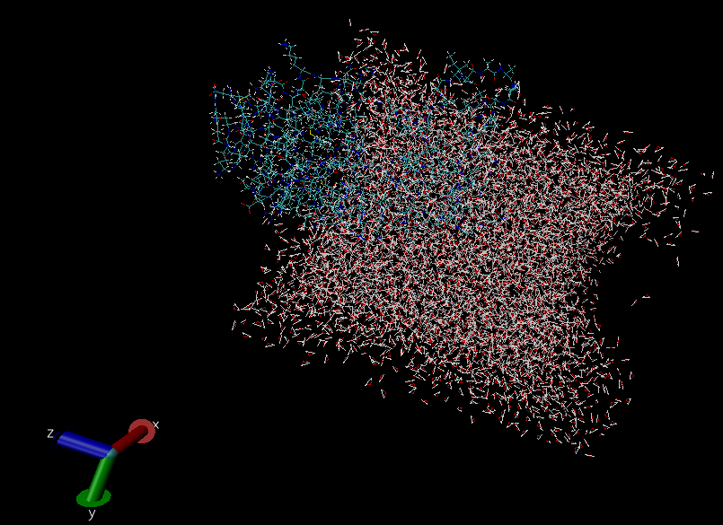
By the way, I've just finished another 10 ns of MD production, and attached
below is a screen shot of the water box after 30 ns MD production
I don't know why this gap on the right side of the water box was created..?
Thanks a lot for your time!
On Fri, Aug 14, 2015 at 1:38 PM, Jason Swails <jason.swails.gmail.com>
wrote:
> On Thu, Aug 13, 2015 at 8:36 PM, Amber mail <amber.auc14.gmail.com> wrote:
>
> > Dear AMBER users,
> >
> > I am performing a MD simulation using AMBER12 under the ff99SB force
> filed.
> > Initially, the structure was neutralized and then solvated using TIP3P
> > water model.
> >
> > After the minimization stage, a 50ps of MD simulation was performed from
> 0K
> > to 100K. The system is then heated up in increments of 25K with 50ps of
> MD
> > simulation at each temperature increment until the desired temperature of
> > 310K was established.
> >
> > This the control file for heating (0-100)K
> >
> > Heat
> > > &cntrl
> > > imin=0,
> > > ntx=1,
> > > irest=0,
> > > nstlim=25000,
> > > dt=0.002,
> > > ntf=2,
> > > ntc=2,
> > > tempi=0.0,
> > > temp0=100.0,
> > > ntpr=100,
> > > ntwx=100,
> > > cut=8.0,
> > > ntb=2,
> > > ntp=1,
> > > ntt=3,
> > > gamma_ln=1.0,
> > > tautp=1.0,
> > > taup=1.0,
> > > pres0=1.01325,
> > > nmropt=0,
> > > ig=-1,
> > > iwrap=1,
> > > /
> > >
> >
> > A 50 ns of MD simulation is going to be performed at 310K. Till now, I
> have
> > got 20 ns out of 50 ns. This is the control file for the production step
> >
> > Production
> > > &cntrl
> > > imin=0,
> > > ntx=5,
> > > irest=1,
> > > nstlim=5000000,
> > > dt=0.002,
> > > ntf=2,
> > > ntc=2,
> > > temp0=310.0,
> > > tempi=310.0,
> > > ntpr=5000,
> > > ntwx=5000,
> > > cut=8.0,
> > > ntb=2,
> > > ntp=1,
> > > ntt=3,
> > > gamma_ln=1.0,
> > > ig=-1,
> >
> > nmropt=0,
> > > iwrap=1,
> > > /
> > >
> >
> > The problem is that a part of the protein is leaving the water box after
> 20
> > ns of the MD production
> >
> >
> >
> > Please correct me If I am wrong, since I used the wrapping option
> > (iwrap=1), the water molecules should wrap (surround) any residue in case
> > if it is trying to leave the water box. does this mean that these outer
> > residues are being simulated now in vacuum?!
>
>
> No, this is not what it means. Your simulation is still being simulated
> under periodic boundary conditions, which means that *all of space* is
> filled with copies of particles translated by whole periodic box vectors.
> Consider a basic cartoon of periodic boundary conditions (e.g.,
> http://dynamomd.org/images/PBC.png). Note that in that image, there are
> an
> *infinite* number of choices you can make about how to define the "primary
> box". You can translate it arbitrarily in both dimensions (all three
> dimensions if you have a 3-D periodic system, like in MD simulations) so
> that it cuts through the middle of any of the circles.
>
> One way to define the periodic cell is to put the protein in the center and
> all of the water around it. That is probably what you would most like to
> see, but that's no more "correct" from a simulation perspective than
> translating the box so that the center of mass of the protein is next to
> one of the edges (which means that part of the protein appears to "stick
> out" of the primary unit cell). If you want a different view, you need to
> image your trajectory to achieve it. For 99% of applications, the
> "autoimage" command in cpptraj will give you the "prettiest" unit cell
> representation.
>
>
>
> > If I am right, is setting
> > ntb=2 (boundary conditions) works for this behavior, and there is no
> > problem ?!
> >
>
> No. ntb=2 simply means "use periodic boundary conditions, but let the
> unit cell change size and maybe shape". This happens when you run constant
> pressure simulations. Periodic boundary conditions are periodic boundary
> conditions, whether you set ntb=1 or ntb=2, there's no difference in this
> regard.
>
>
> > Another question regarding the heating stage, below is the plot of
> > Temperature vs. Time before production, I am wondering why the increase
> in
> > the Temperature was not going smoothly and the equilibration did not
> reach
> > at the end of the heating stage (like the results of the tutorials,
> which I
> > performed before)
> >
> >
> > A same pattern (sudden change) was also obtained for the Potential
> energy,
> > Kinetic Energy and the Total Energy (in the heating stage)
> >
>
> That is because the heating occurs rapidly at the start of each stage.
> Generally this isn't a huge problem, but you can use nmropt=1 with
> temperature control to slowly vary the target temperature in order to heat
> the system steadily from low to high temperature in a single simulation.
> There are examples (called "slow heat") in my input file repository at
> https://github.com/swails/Mdins
>
> HTH,
> Jason
>
> --
> Jason M. Swails
> BioMaPS,
> Rutgers University
> Postdoctoral Researcher
> _______________________________________________
> AMBER mailing list
> AMBER.ambermd.org
> http://lists.ambermd.org/mailman/listinfo/amber
>
_______________________________________________
AMBER mailing list
AMBER.ambermd.org
http://lists.ambermd.org/mailman/listinfo/amber
(image/png attachment: Screenshot.png)
